
by Lloyd Butler **
(First published in the journal "Amateur Radio", January 1988 with the approval of Australian Department of Defence)
During the height of activity at Woomera, there were people who ventured into vast areas of uninhabited land in a range 2000 Km long, their only communication, HF radio. Here we discuss the mobile radio equipment they used and the background of its development.
INTRODUCTION
On April 1, 1987, the Laboratories of the Defence Science & Technology Organisation at Salisbury celebrated the 40th anniversary of its first formation as the Long Range Weapons Establishment (LRWE) in 1947. The establishment was formed to support a range at Woomera which experimented with guided weapons, pilotless aircraft and air launched equipment as a joint venture of the United Kingdom and Australian governments. Over recent years, the operation of the range has been gradually phased down and the function of the establishment has changed with several changes in name and departmental control.
During the height of operations at the Woomera range, the establishment was called the Weapons Research Establishment (WRE) and, as shown in figure 1, the range firing area was extended 2000Km over vast areas of uninhabited land to Talgarno on the north west coast.(ref 1). Various parties were required to venture into this land, often as lone individuals who drove Landrover vehicles where there were no roads and who had to survive the harsh environment of the bush for weeks or months at a time before returning to civilization. Amongst these individuals is the name of Len Beadell, well known for his many books published about his experiences in the bush.
People who ventured into the bush came from various sections and departments with various functions to carry out. They included Survey parties, the Reconnaisance Section, National Mapping, Works personnel, Commonwealth Police and Range Security, Native Affairs officers, the range Missile Recovery team and many others. Each of the vehicles used by these parties had to be equipped with HF radio because HF radio communication was the lifeline back to civilization. The purpose of this article is to discuss this mobile radio and in particular the radio transceivers progressively used over the years to do the job.
THE TRANSCEIVERS
Outside the research establishment, what will generally be unknown is that two models of mobile HF transceiver were designed and built by the establishment and provided for the bulk of mobile HF radio installations during the height of activity at the range. Much of the initial discussion concentrates on these transceivers, the basis of their development and their application in the field. Reference will also be made to some of the people involved.
The environment of the bush was harsh and the radio equipment often had to endure extremes of vibration and mechanical shock due to the rough terrain. Added to this were the high temperatures encountered within the vehicle from the hot northern sun and the dust which could get into switches and connectors to cause many problems.
The most harsh treatment was probably given to radio sets installed in the missile recovery vehicles. Considering the endless supply of whip aerials needed for replacement and the extent of tree foliage which finished up in the radio equipment, it would seem that these vehicles were driven straight through the bush to their target just like one would drive a tank.
THE TYPE 1 TRANSCEIVER
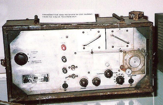
The first transceiver, called the LRWE Type 1, was developed by Ted Peppercorn around the period 1950-1951 (ref 2) and this is shown in figures 2, 3 & 4. The design of the Type 1 unit followed a review of commercial market and defence service sources for a HF transceiver suitable for mobile operation. The Army No 122 wireless set was found to be suitable but setting up and adjustment of this set was complex, requiring the attention of a trained radio operator, hence it was decided to build a more basic unit, simpler to use in the field.


The transceiver was an all valve unit with crystal locked transmitter and receiver, frequency changeable within the range of 5 to 8.5 Mhz using plug in crystals. The high voltage supplies were derived from a genemotor, originally designed for the Army No 19 wireless set and operated from the 12V vehicle battery. HT voltages were 450v, used for the RF power amplifier and 250V for the remainder of the transmitter stages and the receiver. Battery load current was 12.7 amps on transmit and 7.7 amps on receive. Operational mode was either CW or AM.
The circuit diagram for the earlier units constructed is shown in figure 5. These had a valve type 807 as the final transmitter amplifier which delivered an RF output power of 15 watts. Later versions, designated Mark 2, were fitted with a valve type 2E26. In the receiver, two IF stages were used but the designer had aimed at simplicity and not included a pre-mixer RF stage. A high IF frequency of 1600 Khz was employed to compensate for the resulting reduction in image response but this also set the bandwidth quite wide at 12 Khz. The output tuning and coupling circuit for the transmitter was also used as tuning and coupling for the receiver.
 |
Vehicles were provided with whip aerials for mobile operation and wire dipoles to hang from available trees for stationary operation. Dipoles were fed via twin wire feeders cut to an electrical half wavelength to ensure that the dipole centre impedance was reflected at the transmitter, independent of the dipole to feeder mismatch. The feeder cable was ordinary PVC household twin cable and according to Ted Peppercorn (ref 2), was quoted by the manufacturer to have a characteristic impedance of 160 ohms and a loss per 100 ft of 3 dB at 45 Mhz. Obviously, its loss would be quite low at the low frequency end of the HF band, a fact which might surprise many who would discard it as unsuitable for aerial use. A disadvantage of the dipole was that a separate one had to be carried for each frequency channel required.
Whip aerials were base loaded as helical whips were not in common use at that time and whips with centre loading coils were too top heavy to stand up to the rough treatment through the bush. A conventional base loading coil is shown in figure 6 fitted into the whip. Later installations had a tapped loading coil fitted in a switch box adjacent to the whip base, so that the loading inductance could be selected to suitably match the aerial for the channel frequency used. (Refer figure 7).


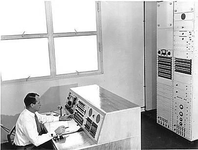
Exactly how many Type 1 transceivers were manufactured is not known but by June 1960 there were 50 mobile stations recorded as working into base stations at Woomera (VL5BW, figure 8), Giles meteorology station (VL6DJ) in the centre of Australia and Talgarno (VL6DU) on the north west coast. Of these 50 mobile stations, 37 were Type 1 transceivers. For the record, the other 13 were Traegar Type 51MA valve transceivers - Refer Figure 7A. (Alf Traegar is of course famous for his early pedal radio and his connection with the Royal Flying Doctor Service.)
To make the HF communications picture complete, there were also AWA 5A teleradio transceivers installed for early warning purposes at six station homesteads in the range area and a base station at Salisbury (VL5BV) which sent timing signals to Woomera and provided an emergency communications link between the two locations when required. Some mobile stations also operated into the Royal Flying Doctor HF network as well as the range network.
Some personalities associated with early installations of the Type 1 transceiver were Bill Lloyd and Fred Brown. (Fred was later responsible for radio maintenance at Woomera base). Another was Lofty Turner who spent many hours in the screened room at Salisbury clearing faults on Type 1 units and carrying out alignment.
In later years, an attempt was made to decrease the bandwidth of the Type 1 receiver by using a second stage of frequency conversion to an IF frequency of 100 Khz. A number of transceivers were modified by the addition of a transistorised conversion module but full scale conversion was superceded by the development of the Type 2 transceiver.
SKIP ZONE
HF communication relies on the ionosphere and communication difficulties were sometimes experienced because of the skip zone. Recovery teams required continuous communication as they proceeded down range and signal fade out was initially experienced as they moved out of the ground wave region into the skip zone. Communication was improved by installing remote receivers, connected via landlines, part way down the range at the Knoll and later further down at Mirikata. Communication in the reverse direction was also assisted by locating the recovery channel transmitter some distance to the rear of the range proper at Woomera technical area.
THE TYPE 2 TRANSCEIVER
As years progressed, germanium transistors commenced to replace valves in low frequency applications. During the period 1958-1959, small signal RF transistors, extending operation into the HF spectrum, became available to open the door for the design of a new transceiver, all transistor except for RF power amplification. Such a design would result in considerable reduction in battery load current in the mobile vehicle. At the time, there was no available transistorised unit on the market and the writer, Lloyd Butler, set about the design and development of a new unit based on the existing state of the art transistor technology. (Ref 3). The new unit was to be called the WRE Type 2 transceiver.
Quite apart from the advantage of reduced battery load, there were a number of other reasons why a new unit needed to be developed. There was a proven need for a wider frequency range than available in the Type 1 unit to allow for changing conditions of the ionosphere and the wide range of different distances covered. Receive capability up to 20 Mhz was desirable to allow survey parties to tune the higher frequency channels of WWV. An additional amenities service could also be provided by the addition to the receiver of the MF broadcast band. There was scope for improvement in the receiver performance. Finally the Type 1 transceivers were starting to respond unfavourably to the rough treatment they were getting and there was a clear need to give attention to prevention of damage from vibration, mechanical shock and dust.
With the help of John Langman, who also played an important part in the development, a prototype was assembled to the following specification:
Transmitter - 3 crystal locked channels within the range 2-5 to 12 Mhz .RF power 10 - 12 Watts.
Receiver - Tunable range 2. 5 to 20 Mhz & 500 to 1500 Khz. Also two crystal locked channels within the range 2.5 to 12 Mhz
Mode - R/T or CW
Battery load - Receive only 18 mA.
Standby 820 mA
Transmit 5 A
The circuit of the Type 2 transceiver is shown in figure 9a/b. The receiver, modulator and transmitter power supply were all transistor, but at that stage of the technology, power RF transistors were yet to be introduced and use of RF power valves in the transmitter was still the only option. There were problems in maintaining temperature stability in the early germanium transistors of that era and considerable attention was given to this in the circuit design resulting in satisfactory performance to above 70 degrees C. At that point in time, such a temperature was considered to be quite an achievement for germanium transistors.

|
The faithful 2E26 RF power amplifier was again used but a more complex aerial loading circuit was included to allow internal presetting of the matching, for each channel, to a single long wire. The circuit was duplicated for whip aerial operation so that neither channel change, nor change from long wire to whip, required any adjustment by the operator. The circuit also eliminated the need for more than one wire aerial when using more than one channel. Use of a long wire was possibly not as effective as the dipole used in the Type 1 transceiver, but the thoughts were that it was difficult enough to find single trees for aerial support in parts of Central Australia, let alone two trees spaced at a suitable distance to hang two ends of a dipole. For the transmitter oscillator and power amplifier driver stages, special quality ruggedised versions of the 6AU6 and 6AQ5 valves were used.
The transistor HT power supply only operated on transmit, delivering 35OV to a fully loaded transmitter at a current of 100 mA. Power supply efficiency was 70 %.
The receiver employed an RF stage and two IF stages operating at a frequency of 455Khz. Sensitivity for the HF bands was within 1 to 2 microvolts for 6dB signal to noise ratio, degrading a little at temperatures approaching 70 degrees C. Image performance was good except at frequencies approaching 20 Mhz, not unexpected for an IF frequency of 455Khz.
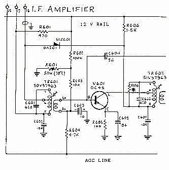
An interesting innovation was used in the RF amplifier and first IF amplifier, the later of which is shown in figure 10. In this circuit, DC feedback from the emitter is reduced by restricting the value of emitter resistor with resultant loss in temperature stability. This is compensated by the inclusion of a thermistor in the base bias circuit. The DC feedback works against the AGC control voltage and reduction of that feedback results in a dramatically improved AGC characteristic.
ENVIRONMENTAL TESTING
Assembly of a prototype led to the manufacture of two production models of the transceiver and the first of these was subjected to a range of environmental tests to simulate field conditions including vibration, shock, temperature and dust tests. Available within the-Establishment for this purpose was probably the best equipped environmental test facility in the southern hemisphere. (This facility still exists, as part of the Advanced Engineering Laboratory, providing an excellent service). A second production unit was tested operationally in a number of field trials.
In carrying out environmental tests, the help of Eric Grant from the environmental test section must be acknowledged. One interesting aspect of the programme was a test carried out on a Landrover vehicle itself. With portable vibration test equipment on board, Eric and the writer sought out the roughest tracks which could be found around Salisbury to resolve just what vibration components were generated in the vehicle. This was necessary to select vibration mounts which reduced best those components which had the highest acceleration and did the most damage. For a given amplitude, the higher the vibration frequency the higher the acceleration and it was the high frequency high acceleration components which had to be reduced. This was at the expence of tolerating high amplitude but low acceleration low frequency components. What appears visually to be the best vibration isolation does not necessarilly lead to the best result and without suitable vibration test equipment, selection of a mounting system would have been guesswork.
Before finalising drawings of the transceiver, it was necessary to look for components or parts of the assembly that take on mechanical resonance at a vibration frequency. This is done by mounting the unit on a vibration table and sweeping the vibration frequency through the anticipated range. Resonance is observed by flooding the unit with light from a stroboscope, chopped at a frequency near that of the vibrator. Components or sections of the assembly which show resonance must be restrained to prevent mechanical fatigue and consequent changes must be made to the manufacturing procedure. A lesson on environmental testing is not intended but the discussion does give some background to the work carried out before manufacturing detail of the transceiver was finalised.
PRODUCTION
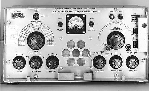
A total of 29 Type 2 transceivers were manufactured apart from the prototype. Of these, 8 were manufactured by WRE workshops and 21 were manufactured under contract by Amalgamated Wireless (Australasia) Ltd (AWA). The AWA units were similar to the WRE units except for minor construction details made to suit their own production system. (A typical unit is shown in figures 11 to 13.) The first two WRE units were made in 1960. These were followed by the AWA units which came off the production line in 1962 and a further 6 WRE units which were made later on.


Personalities who assisted with the development and testing of the Type 2 transceiver included John Langman and Vin Agius. John, in particular, stayed with the work of the Type 2 to see them all tested and installed long after the writer had moved to other fields of endeavour. Drawings were prepared for production by draughtsmen Dick Osborne and Mike Winterson.
Records show that by October 1967, 73 AM HF radio transceivers were in service around the range. By this time, Traegar was well into the production of a transistorised version of their transceiver and a number of Traegar types TM2 and TM3 were acquired to supplement the numbers of WRE Type 2 sets and replace some of the Type 1 sets. Consideration had been given to granting a contract for the manufacture of a further 20 Type 2 units but with commercial transistorised transceivers then on the market, purchase of the latter appeared more cost effective.
The idea of the long wire, visualised for the Type 2 transceiver, suffered some change as vehicle installations proceeded. Traegar supplied a 35 ft telescopic whip which was put together from a number of short tubular sections and which could be carried in the vehicle. A number of these whips were purchased for the Type 2 installations instead of, or to supplement, the use of the long wire in fixed location operation. The whip base support could be driven into the ground for support or the whip otherwise supported by fixing to the side of the vehicle. The high whip, of course, eliminated the need for those rare trees. Operationally, the high whip would have been ideal for ground wave and long hop paths but not as good as the horizontal wire for short hop high angle paths. One danger of the high whip was the possibility that it could be erected near power lines, with the potential for electric shock from accidental contact with the lines. There is one disastrous accident on record to bear testimony of this.
THE TRAEGAR SETS
As far as the Type 2 transceiver was concerned, the attention to environmental testing and vibration isolation paid off and they withstood the vehicle vibration better than the Traegar units. Notwithstanding this, towards the end of the AM era, the Traegar Type TM3 (refer figure 14) replaced a number of Type 2 units for various reasons which will be discussed in the following paragraphs:
 |
Firstly, the Type 2 unit was designed to work with positive battery earth, the general standard in Landrover vehicles at the time of design. As time progressed, a number of new vehicles purchased were fitted with negative earth and the Traegar units were favoured because they had provision for earth on either rail. Some Type 2 units were modified for negative earth but to do this was probably an intricate process.
Another reason for changing to the Traegar unit was that it was smaller than the Type 2 and could be easily fitted under the vehicle dashboard.
A further problem encountered with recovery vehicle installations was the variation in load impedance presented to the transceiver output by the short whip. A reason for this was that when the vehicle was mobile, the top of the whip was tied down to reduce damage from trees passed and this resulted in a change in the electrical characteristics of the whip. Another reason was variation in contact resistance of the whip joints which in turn, varied the antenna loss resistance. The Type 2 loading system was based on pre-set adjustment with the idea that the unskilled operator be relieved of the task of aerial tuning. Apparently, the Traegar unit suited the application better because a simple aerial tuning adjustment was available to the operator which could be used to correct for the impedance change.
The Traegar units could transmit on frequencies in the range of 1.5 to 10 MHz and receive in a range of 1.5 to 16 MHz plus the broadcast band. A disadvantage was that plug in units were still used to change transmit frequencies, or change receiver bands, as had been the case for previous Traegar all valve transceivers. Units Type TM2 and TM3 were similar except that the TM3 had the feature of a quick heat RF power valve which eliminated valve heater load on receive. RF power output of the TM3 could be as high as 25W with 14V battery supply.
Records updated in 1976 showed a mixture of WRE Type 2 transceivers, Traegar Type TM2 and TM3 transceivers and a few Traegar Type 59M10 transceivers. The 59M10 was an all valve unit and it is not clear how it was introduced or why it was still in the network at that late stage. (It is probable that the 59M10 units were surplus from one of the other Departments which provided support services to the range.).
THE RECENT YEARS (As known at the date of writing this article in 1987)
A lot of water has passed under the bridge since those early days of the Woomera range. The range still carries out a few trials but today it is but a mere shadow of its former self. The HF radio change to single sideband was completed in 1978 some 28 years since the first Type 1 transceiver was developed. At that stage, time for our AM mobile radios ran out.
Planning for change of the whole Range HF system to single sideband commenced as early as 1970, taking some 8 years to finally complete. The mobile radio part of the network now consists of approximately 16 Codan SSB transceivers Type 7515 which have a rated output of 5OW peak envelope power, somewhat of an improvement on the old AM units which had equivalent single sideband powers of around 3 to 5 watts. The Codan 7515 can operate on up to 10 channels within the frequency range of 2 to 11 Mhz. Aerials used are helical whips and mobile stations are expected to operate to other stations at distances up to 400 Km.
Future plans anticipate the use of a number of Codan Type 8525 transceivers which are state of the art synthesised SSB units with such features as automatic aerial tuning.
After 37 years of HF radio our story ends. Particular reference has been made to the two early transceivers developed in our Establishment during the 1950 - 1960 years, a period in which the writer was closely associated with the radio communications of the range. To complete the picture for more recent times, much of the information recorded is the result of helpfull discussions with other people who have been involved, such as John Langman, Vin Agius, Tony Bell and Geoff Fuss.
Looking back over those years during the peak of activity, we see a mobile radio network some 70 units strong, communicating over vast areas of uninhabited land in a range 2000 Km long. Where else in the world would such a network be found ?
Most of those old AM transceivers have been disposed of now and one just has to wonder where they might now be gathering dust, or what other fate they might now have met.
REFERENCES
1. A brochure of information, Weapons Research Establishment, Dept of Supply, Australian Defence Scientific Service. 3rd edition, April 1961.
2. A range communications design study and technical description of high frequency transceiver Type 1 Mark 1 - A.E.Peppercorn. Long Range Weapons Establishment - Technical Memorandum E/M12, Oct 1951.
3. The WRE Type 2 HF mobile transceiver. An outline of the development of a prototype. - A.L.Butler - Weapons Research Establishment Technical Memorandum ENG3, May 1960.
4. The Woomera communications network - E.B.Davis - Electrical & Mechanical Engineering Transactions, The Institution of Engineers, Australia - Nov 1961.
5. Instruction Book, Layouts, & Circuit Diagrams for the WRE Type 2 HF Transceiver: **THE
AUTHOR Lloyd Butler was
employed on developmental work in the Communications &
Electronic Engineering Division of the Advanced Engineering
Laboratory, Defence Science & Technology Organisation,
Salisbury. During the period 1955 - 1961 he was associated with the
provision of HF and VHF radio communication facilities for the
Woomera Range. As part of this work, he was responsible for the
design and development of the WRE Type 2 HF transceiver discussed
in this article.
(a) Instruction Book
(b) Layouts
(c) Circuits
